System Introduction
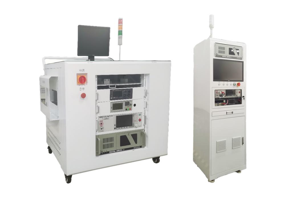
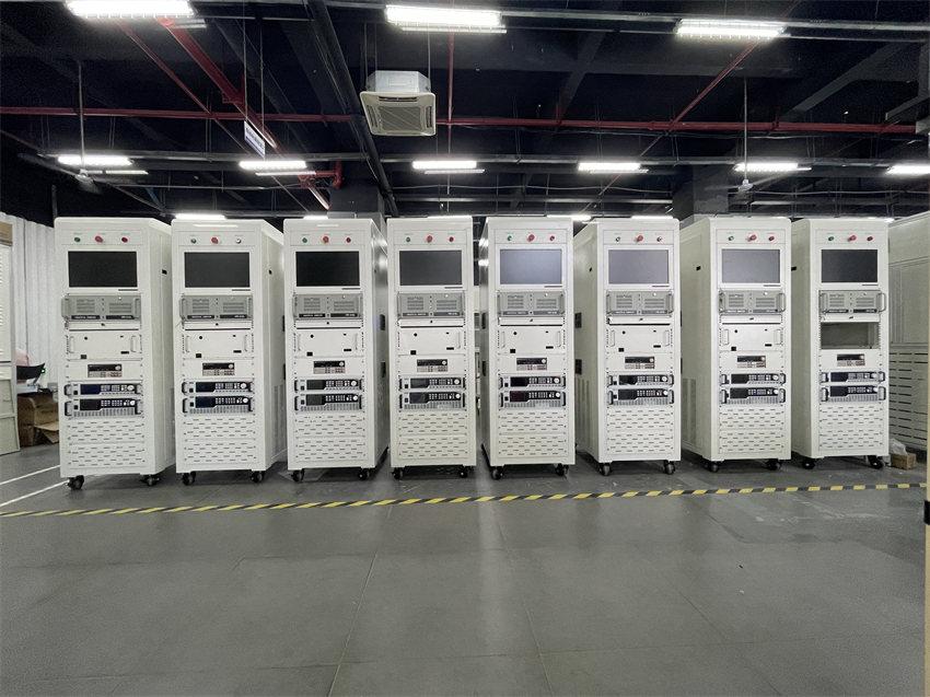
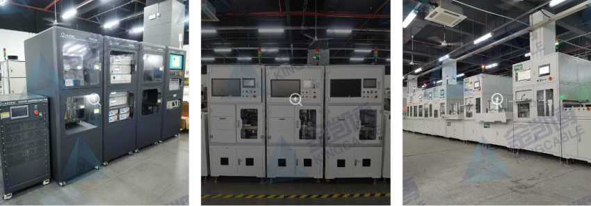
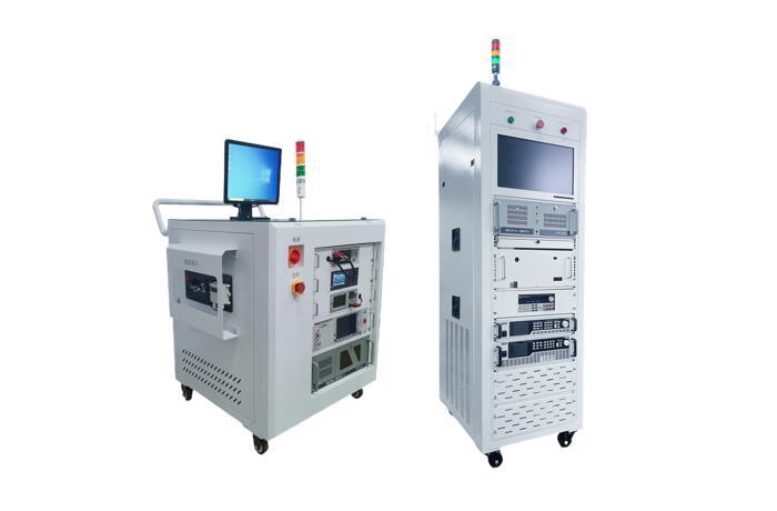
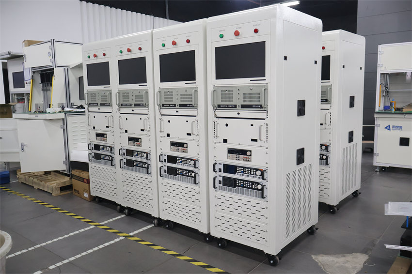
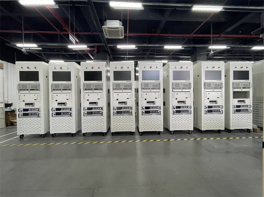
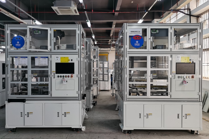
The EOL test system (battery tester) is designed based on an open hardware and software architecture, and can flexibly expand hardware according to customer needs and quickly establish test programs. The battery tester can perform a variety of basic test items, greatly improving the ease of use of the system, and providing users with universal, flexible, and standardized battery cell/module automatic test system solutions as much as possible. It can realize intelligent testing of battery pack module/battery cell insulation, withstand voltage, and total internal resistance. The equipment automatically determines whether the test is qualified, automatically records test data, and automatically uploads it to the MES system, which can achieve matching of production rhythms of previous and next processes.
Test items
The functional test items that the EOL test system needs to implement and the implementation methods are described as follows:
1. PACK main positive electrode to shell insulation/voltage test
This function mainly tests the insulation resistance between the main negative pole of the module's main circuit output and the module shell. To test this function, the system needs a Hipot tester (KIKUSUI TOS9303-LC);
Set the Hipot tester to insulation resistance mode. The Hipot tester applies a DC voltage of 50V-1000V between the negative pole of the module main circuit output and the module housing. The Hipot tester directly measures the insulation resistance of the device and uploads the test results to the host computer.
The main testing process is as follows:
a) Close the corresponding Hipot test relay;
b) Set the Hipot test parameters;
c) Start Hipot (starting voltage/boost time/voltage holding time/test time/discharge time are adjustable);
d) Obtain test data;
e) result reading;
f) Disconnect the contactor;
Set the Hipot tester to DC withstand voltage mode. The Hipot tester applies a DC voltage of 500V-5000V between the negative pole of the module main circuit output and the module housing. The Hipot tester directly measures the withstand voltage current of the device and uploads the test results to the host computer.
The main testing process is as follows:
g) Close the corresponding Hipot test relay;
h) Set the Hipot test parameters;
i) Start Hipot (starting voltage/boost time/voltage holding time/test time/discharge time are adjustable);
j) Obtain test data;
k) result reading;
l) Open the contactor.
Finally, based on e and k, assess whether the main negative electrode Hipot is normal;
2. Battery main negative electrode to shell insulation/voltage test
This function mainly tests the insulation resistance of the main positive pole of the module's main circuit output to the module shell. Testing this function requires the system-configured Hipot tester (KIKUSUI TOS9303-LC);
Set the Hipot tester to insulation resistance mode. The Hipot tester applies a DC voltage of 50V-1000V between the positive output of the module main circuit and the module housing. The Hipot tester directly measures the insulation resistance of the device and uploads the test results to the host computer.
The main testing process is as follows:
a) Close the corresponding Hipot test relay;
b) Set the Hipot test parameters;
c) Start Hipot (starting voltage/boost time/voltage holding time/test time/discharge time are adjustable);
d) Obtain test data;
e) Reading of test results;
f) Disconnect the contactor;
Set the Hipot tester to DC withstand voltage mode. The Hipot tester applies a DC voltage of 500V-5000V between the positive pole of the module main circuit output and the module housing. The Hipot tester directly measures the withstand voltage current of the device and uploads the test results to the host computer.
The main testing process is as follows:
g) Close the corresponding Hipot test relay;
h) Set the Hipot test parameters;
i) Start Hipot (starting voltage/boost time/voltage holding time/test time/discharge time are adjustable);
j) Obtain test data;
k) result reading;
l) Open the contactor.
Finally, based on e and k, assess whether the main positive electrode Hipot is normal;
3. PACK communication function test
This function mainly tests the communication function of BMS PACK CAN. The EOL tester receives and analyzes the CAN frames sent by the BMS system through PACK CAN to determine whether the communication function is normal. Whether the PACK communication function is normal is determined by whether the message information is within a reasonable range.
The main testing process is as follows:
a) The EOL tester supplies power to the BMS, receives and analyzes the message information sent by the BMS;
b) message information judgment and result determination;
c) Disconnect the power supply to the BMS.
4. Static communication function test
This function mainly tests the communication function of the internal CAN of the BMS. The EOL tester receives and analyzes the CAN frames sent by the BMS system through the internal CAN to determine whether the communication function is normal. Whether the internal communication function is normal is determined by whether the message information is within a reasonable range.
The main testing process is as follows:
a) The EOL auxiliary tester supplies power to the BMS, receives and analyzes the message information sent by the BMS;
b) message comparison and result determination;
c) Disconnect the power supply to the BMS.
5. BMS single cell voltage consistency test
This function mainly tests the consistency of the single cell voltage measured by the BMS to determine whether the BMS sampling is accurate or whether the consistency of the PACK is good.
The main testing process is as follows:
a) The EOL auxiliary tester supplies power to the BMS;
b) Read the voltage value of each cell through CAN communication, use the custom variables to first calculate the maximum cell voltage, the minimum cell voltage, and then calculate the maximum voltage difference to determine whether the value is within the set range;
c) Result determination;
d) Disconnect the power supply to the BMS.
6. BMS cell temperature consistency test
This function mainly tests the consistency of the monomer temperature measured by the BMS to determine whether the BMS sampling is accurate or there is an abnormality in the PACK.
a) The EOL auxiliary tester supplies power to the BMS;
b) Read the temperature data of each monomer through CAN communication, use custom variables to first calculate the maximum monomer temperature, the minimum monomer temperature, and then calculate the maximum temperature difference to determine whether the value is within the set range;
c) Result determination;
d) Disconnect power to the BMS.
7. BMS total voltage accuracy test
This function mainly tests the accuracy of the total voltage of the BMS. It mainly tests the total voltage sampled by the BMS and the accuracy of each monomer.
The voltage accumulation value is compared with the voltage sampled by the PACK test cabinet to determine whether the accuracy meets the requirements.
The main testing process is as follows:
a) The EOL auxiliary tester supplies power to the BMS;
b) Close the corresponding contactor of the EOL auxiliary tester;
c) Through CAN instructions, close the main positive and negative contactors and measure the PACK port voltage U1;
d) Through CAN communication, read the total PACK pressure U2 and the voltage value of each monomer measured by the BMS, calculate the cumulative value of each monomer voltage U3, and determine whether the difference between U1 and U2, U3 is within the set range;
e) Result determination;
f) Disconnect the main positive and negative contactors through CAN instructions;
g) Disconnect the EOL auxiliary tester contactor;
h) Disconnect power to the BMS.
8. Auxiliary circuit test
This function mainly tests whether the on and off state of the contactor of the PACK auxiliary power supply interface is normal. In the on and off states of the contactor, the terminal voltage of the PACK auxiliary power supply interface is tested to see if it is the set value to determine whether it is normal.
The main testing process is as follows:
a) The EOL auxiliary tester supplies power to the BMS;
b) Close the corresponding relay of the EOL auxiliary tester;
c) Close the contactor of the auxiliary power supply interface through CAN instructions, and use the high-voltage acquisition module to measure the voltage of the auxiliary power supply port to determine whether the voltage is within the set range;
e) Result determination;
f) Disconnect the relay of the EOL auxiliary battery tester;
g) Disconnect the BMS power supply.
9. Heating film resistance test
This function mainly tests whether the heating film can work normally. It can be judged whether it is normal by testing whether the resistance of the heating film is the set value.
The main testing process is as follows:
a) The EOL auxiliary tester supplies power to the BMS;
b) Select the resistance range of the multimeter;
c) Close the corresponding relay of the EOL auxiliary tester;
d) Use a 6.5-digit multimeter to measure the resistance of the heating film to determine whether the resistance is within the set range;
e) Result determination;
f) Disconnect the relay of the EOL auxiliary tester;
g) Disconnect the BMS power supply.
10. Heating film resistance test
This function mainly tests whether the PACK heating circuit functions normally. Power the heating circuit through the BTS, and compare the heating current measured by the BMS with the heating current measured by the BMS to determine whether it is normal.
The main testing process is as follows:
a) The EOL auxiliary battery tester supplies power to the BMS;
b) Close the heating film contactor through CAN command;
c) Start the BTS and run the constant current charging condition according to the set process;
d) Read the heating current measured by the BMS through CAN communication and compare it with the heating current measured by the BTS;
e) Result determination;
f) Disconnect the heating film contactor through CAN command;
g) Disconnect the BMS power supply;
11. BMS addressing function test
This function mainly tests the compilation function of the PACK BMS slave control board;
a) Supply DC 24V normal power to BMS;
b) Use a multimeter to detect the voltage between 0V and the addressing line, which must be less than DC1V;
c) Send the addressing message, use the multimeter to detect the voltage between 0V and the addressing line, and the requirement is DC>23V;
—————————————————————————————————————————————————————————
Hello! The above product information only lists some of the main test functions. All items supported by the equipment are not listed in detail here.
If you need to obtain customized solutions or company introduction materials, please contact mobile phone & WeChat: +86 13538109318
Click the picture below to view more customer cases


