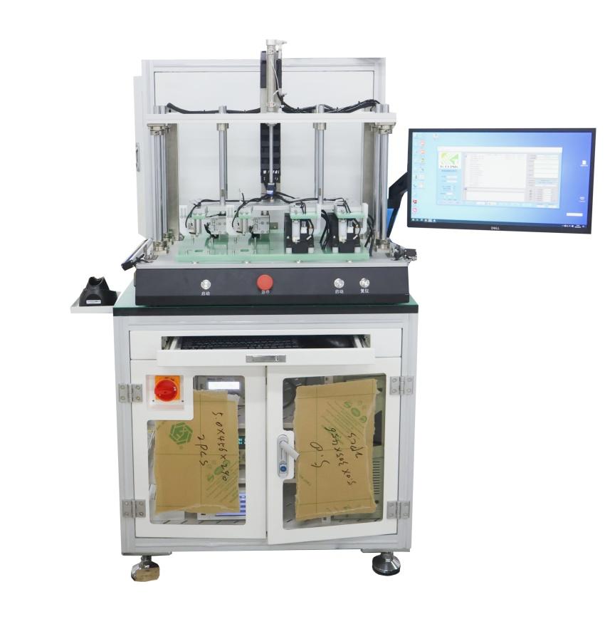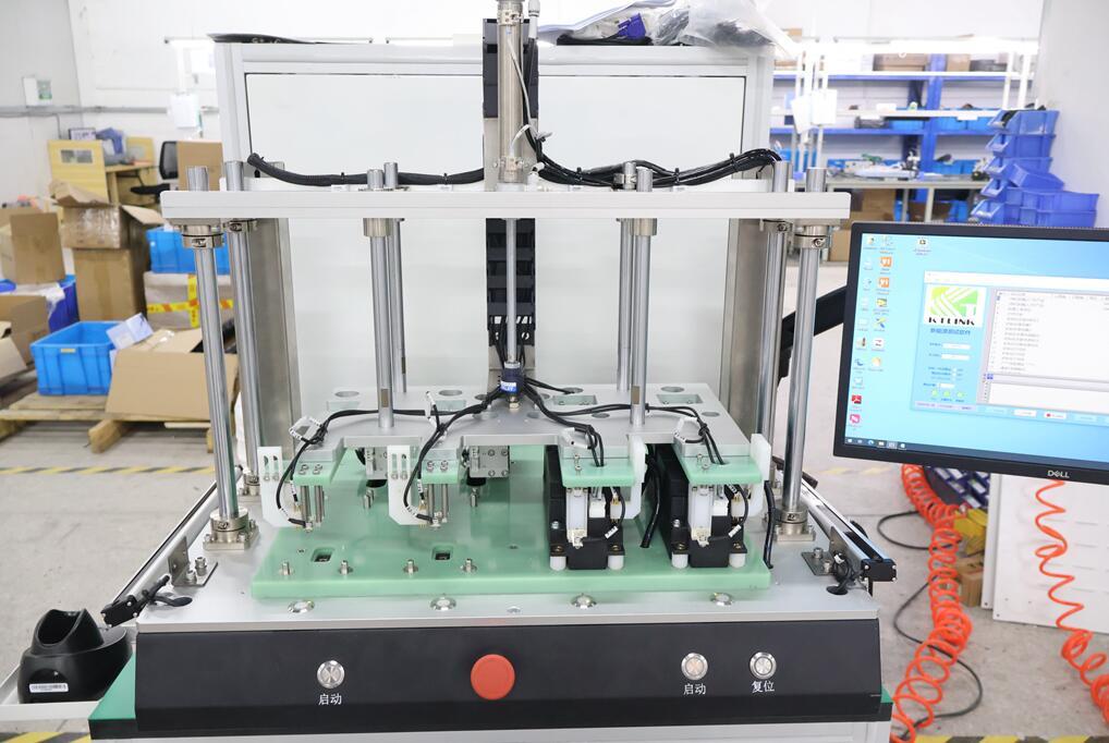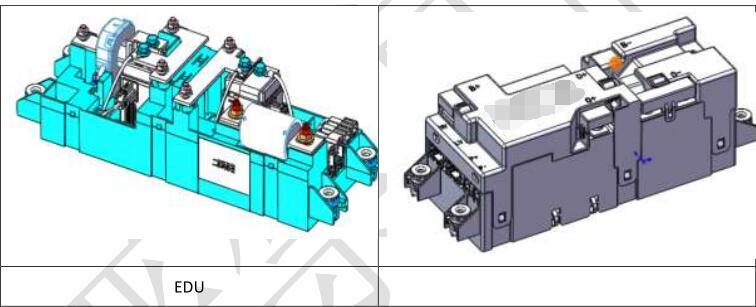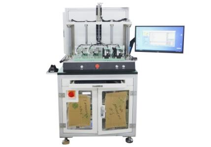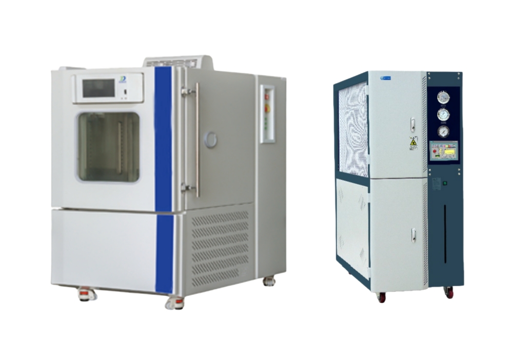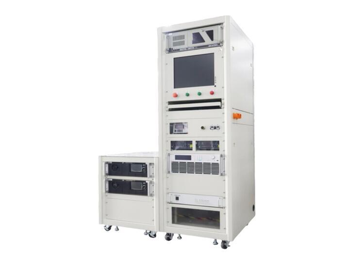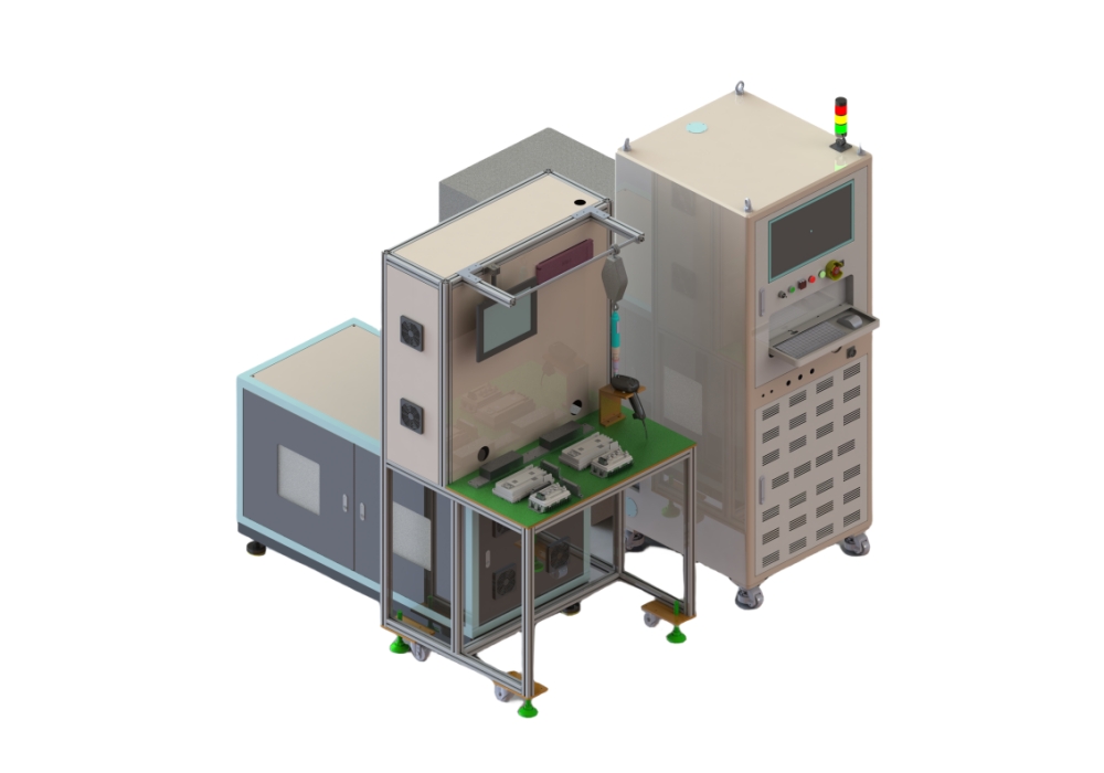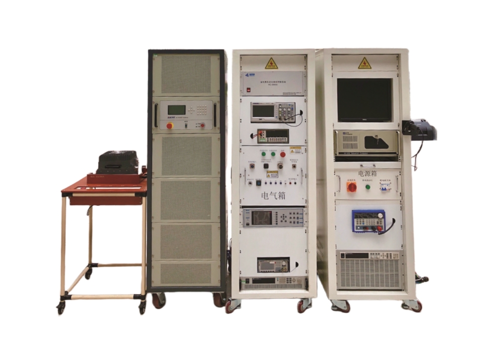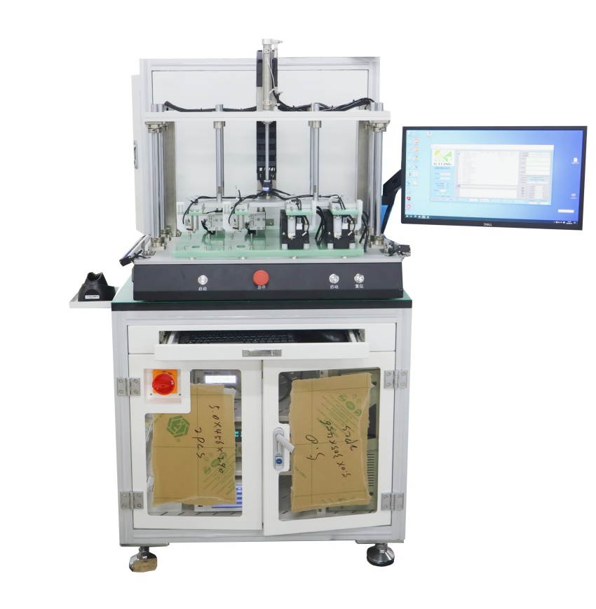
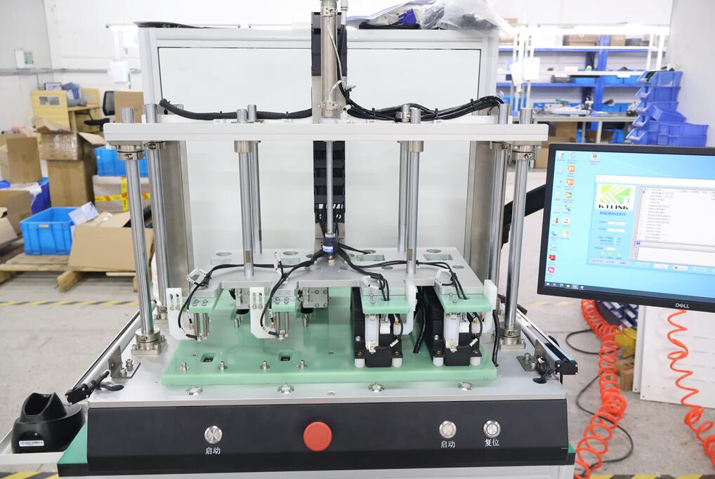
System Composition
This test equipment for electronic is a customized standard test platform for BDU EOL safety and conduction performance testing. Its core is to use various instruments (multimeter, internal resistance tester, safety tester, power supply), combined with online (offline) cabinets, probes, production line PLC interaction, etc., and use LABVIEW virtual instrument technology to automatically test related functions and save the test results to the database.
Test items
| Test items | Require | Test conditions |
| Insulation test | Insulation value meets requirements DC1000V@10s, voltage rise time 1s, fall time 1s); meets the requirements | 1 When the relay is not energized: test the insulation resistance between the pre-charged positive electrode and the shell, and the pre-charged negative electrode respectively. 2 When the relay is not closed: test the insulation resistance between the pre-charged negative electrode and the shell, and the pre-charged positive electrode respectively. |
| Withstand voltage test | Leakage current meets the requirements DC1000V@10s, voltage rise time 1s, fall time 1s); meets the requirements | 1. When the relay is not closed: test the withstand voltage between the pre-charged positive electrode and the shell, and the pre-charged negative electrode respectively, and record whether the test leakage current meets the requirements; 2 When the relay is not closed: test the withstand voltage between the pre-charged negative electrode and the shell, and the pre-charged negative electrode, and record whether the test leakage current meets the requirements. |
| On/off test | Resistance is within the required range | 1. When the power is off, close and open the relay to measure the continuity of the circuit. When the relay is open, the circuit is required to be open, and when the relay is closed, it is required to be conductive. 2. Measure the resistance between each wiring port and ground respectively, which should be consistent with the schematic diagram and without wrong connection or open circuit; 3. Measure the pre-charge resistance of the pre-charge resistance circuit and find it is within the designed resistance range. |
| Voltage drop | Voltage is within specification | Close the relay, pass current, and detect the voltage drop between each contact |
| Relay function test | Detect the resistance between each contact | Can be tested simultaneously with loop resistance |
| Current accuracy detection | Deviation value requirements meet the requirements | In charging state: comparison between power supply output current and Hall detection current (the device has the function of collecting Hall voltage, and the chip Hall needs to have the function of converting analog signals into digital signals for easy judgment by the device) |
| Current direction detection | Direction meets the requirements | In charging state: the direction of the power supply output current is consistent with the direction of the Hall detection (the device has the function of collecting Hall voltage, and the chip Hall needs to have the function of converting analog signals into digital signals for easy judgment by the device) |
| Loop internal resistance test | Meets circuit design value | a. Positive discharge circuit (two circuits): energize the positive relay of the discharge circuit (power on the main positive relay coil), and measure the resistance value of the circuit from PACK+ of the BDU to the positive output of the output terminal. The measured value is required to be less than the design value. b. Discharge circuit negative (two circuits): attract the discharge circuit negative relay (the main negative relay coil is energized), and measure the circuit resistance value between the BDU PACK- and the output negative of the output terminal. The measured value is required to be less than the design value. |
| Scan code to bind | Generate test report and barcode binding | Equipped with a handheld wireless barcode scanner, the test report is generated and bound to the barcode and uploaded to the MES system. The device can automatically display the setting parameters and test data. |
—————————————————————————————————————————————————————————
Hello! The above product information only lists some of the main test functions. All items supported by the equipment are not listed in detail here.
If you need to obtain customized solutions or company introduction materials, please contact mobile phone & WeChat: +86 18033069200
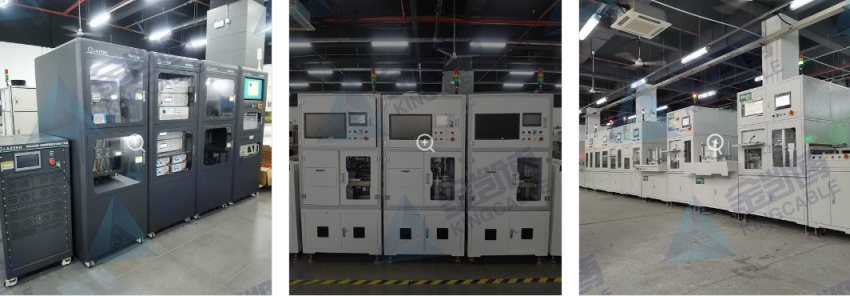
Click the picture below to view more customer cases

